Quick start guide for RZ/V2H RDK
This quick start guide focuses on booting the board using a microSD card, which is the most straightforward method.
Other advanced boot methods, such as xSPI flash, are also supported.
The TFTP + NFS boot method is supported as well but is not covered in detail here.
Preparing the microSD card
To boot the RZ/V2H RDK using a microSD card, you must first flash a bootable Linux image onto it.
There are two options for flashing the image:
Option 1: Flash using bmaptool (Ubuntu) - A faster command-line tool for flashing images using block map files.
Option 2: Flash using Balena Etcher - A user-friendly GUI tool that supports multiple platforms (Windows, macOS, Linux).
Requirements
A host machine for flashing the image:
Ubuntu with
bmaptool, orWindows, macOS, or Linux with Balena Etcher
microSD card: 16 GB or larger. For best performance and compatibility, we recommend using the included 64 GB SanDisk microSD card.
Provided bootable files:
Download WS125-V2HRDKREFZ Robotic Development Kit Software from the Renesas website to your local machine using this link:
Renesas Official RZ/V2H RDK Website
In the
*.zipfile, you can find the following files under theboard_setupfolder:
File name
Description
board_image/Board image files
ubuntu-24.04-server-arm64-rzv2h-rdk.img.xz: Ubuntu 24.04 Server SD card image file containing:
Bootloader
Linux kernel image
Linux device tree file
Ubuntu 24.04 root filesystem
Default credentials:
Username: ubuntu
Password: ubuntu
ubuntu-24.04-server-arm64-rzv2h-rdk.bmap: Block map file for fast flashing withbmaptool
xSPI/Files for booting the RZ/V2H RDK from xSPI
Flash_Writer_SCIF_RZV2H_DEV_INTERNAL_MEMORY.mot: Bootloader file
bl2_bp_spi-rzv2h-rdk.srec: Bootloader file
fip-rzv2h-rdk.srec: Bootloader file
Option 1: Flash using bmaptool (Ubuntu)
bmaptool is a faster command-line tool for flashing images to microSD cards using block map files (bmap). It provides quicker flashing compared to traditional methods by skipping empty blocks and verifying data integrity automatically.
Install bmaptool
On Ubuntu:
sudo apt-get install bmap-tools
Flashing the Image
Insert your microSD card into your machine.
Identify the microSD card device name:
lsblk
Look for your microSD card (e.g.,
/dev/sdb). Make sure to identify it correctly.Warning
Please confirm the microSD card device name carefully. Double-check to avoid overwriting your main disk.
Unmount any auto-mounted partitions on the microSD card:
sudo umount /dev/sdX*
Flash the image directly (no need to extract):
sudo bmaptool copy ubuntu-24.04-server-arm64-rzv2h-rdk.img.xz /dev/sdX
Replace
/dev/sdXwith your actual microSD card device (e.g.,/dev/sdb, not/dev/sdb1).Note
Please ensure that the
.bmapfile is in the same directory as the image file. bmaptool automatically detects the.bmapfile with the same base name.You can also specify it explicitly:
sudo bmaptool copy --bmap ubuntu-24.04-server-arm64-rzv2h-rdk.bmap \
  ubuntu-24.04-server-arm64-rzv2h-rdk.img.xz /dev/sdX
Wait for the process to complete. bmaptool will display progress and verify the image after flashing.
Before removing the microSD card, run:
sync
Option 2: Flash using Balena Etcher
Balena Etcher is a user-friendly GUI tool to flash OS images to microSD cards and USB drives. It provides a simple and safe method.
It supports many OS platforms, including Windows, macOS, and Linux.
Install Balena Etcher
Download and install the software from the Balena Etcher Official Website.
Flashing the Image
Once Etcher is open:
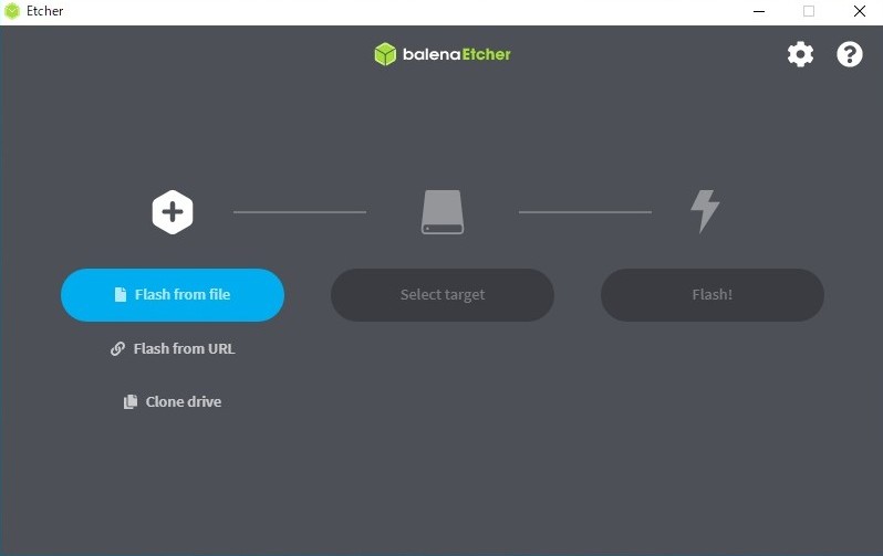
Balena Etcher Application
Select Image: Click
Flash from fileand choose your image file (e.g.,ubuntu-24.04-server-arm64-rzv2h-rdk.img.xz)Select Target: Insert your microSD card into the host machine and choose the correct device.
Note
Please confirm the microSD card device name carefully. Double-check to avoid overwriting your main disk.
Flashing: Click
Flashto begin. Etcher will:Write the image
Validate the image
Automatically unmount the microSD card
Finish: Remove the microSD card safely after Etcher reports successful completion.
Boot Mode Configuration (DIP Switch)
Before powering up the RZ/V2H RDK, make sure the board’s boot mode is configured correctly using the DIP switches.
Switch No. |
RZ/V2H Pin |
Function |
|---|---|---|
1 |
BOOTSELCPU |
Select the cold boot CPU OFF: CM33, ON: CA55 (default) |
2 |
BOOTPLLCA1 |
Input the CA55 frequency at the CA55 cold boot BOOTPLLCA[1:0] |
3 |
BOOTPLLCA0 |
|
4 |
MD_BOOT1 |
Input the boot mode select signal MD_BOOT[1:0] |
5 |
MD_BOOT0 |
|
6 |
MD_BOOT3 |
Select JTAG debug mode OFF: Normal mode (default), ON: Debug mode |
Attention
Always power off the board before changing boot switches.
Boot Mode Support
The board supports two boot options, including:
Boot Source |
Description |
DSW1 Setting |
|---|---|---|
microSD card |
Boot from microSD card |
SD mode |
xSPI |
Boot from xSPI flash |
xSPI mode |
Tip
The serial port is powered by the board, not by the PC USB port.
To see early boot messages, briefly touch JTAG QRESN (PIN10) to GND to reset the board.
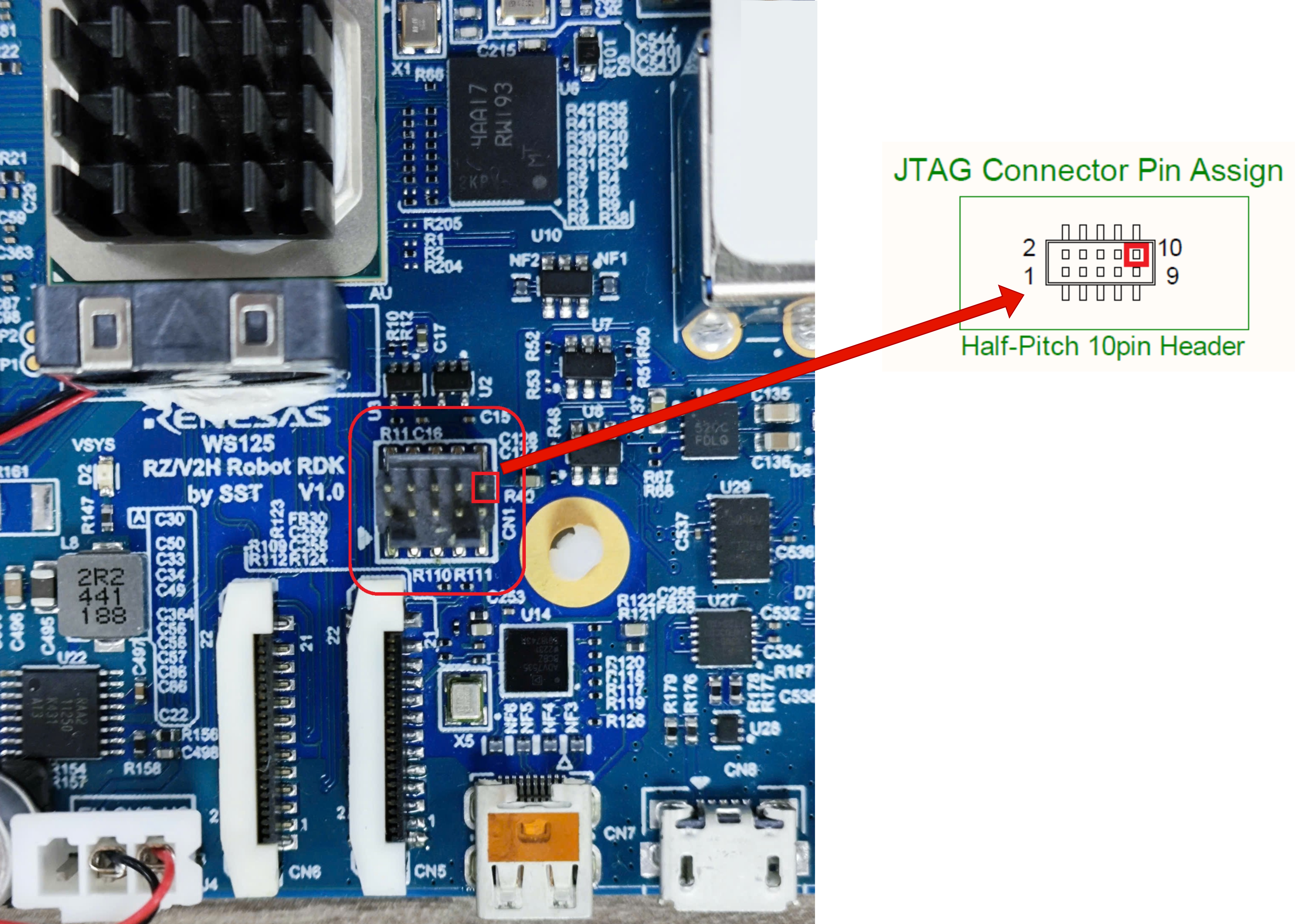
JTAG Reset Pin Example
Note
Before proceeding, ensure that your machine has the necessary drivers and a terminal emulator (MobaXterm, Tera Term, etc.) installed.
The serial communication between the Windows PC and RZ/V2H RDK requires: FTDI Virtual COM Port (VCP) driver
Download and install the Windows version (.exe).
Important
The power supply for the RZ/V2H RDK should satisfy the maximum requirement of 24V / 5A.
The common DC power adapter specifications are:
DC power adapter 12V, 2A. (Included in the package)
DC power adapter 24V, 1A.
Common hardware setup
The following image shows the common hardware setup for both boot modes:
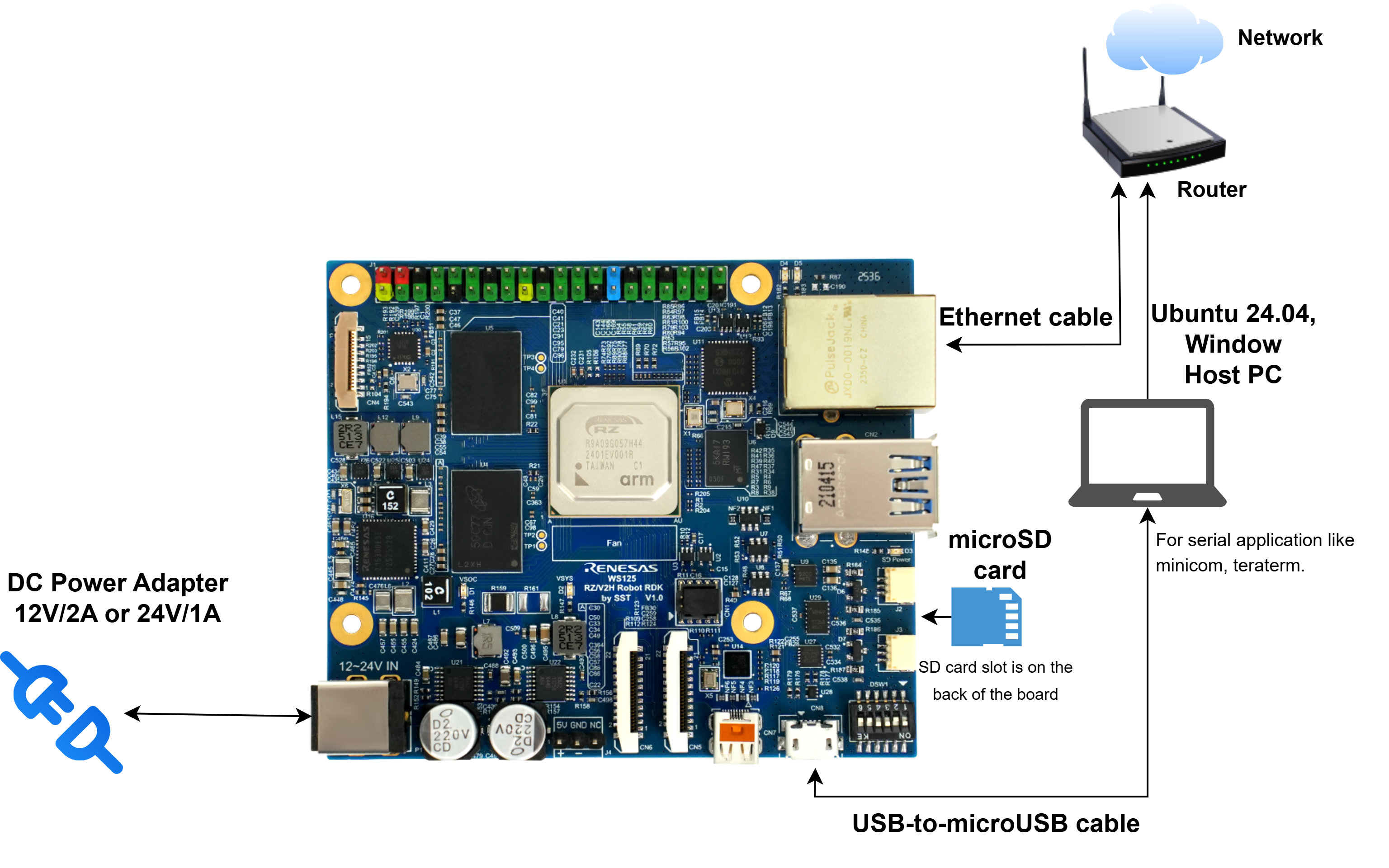
Common Hardware Setup
The setup includes:
Power supply connection
Serial connection for terminal access
Ethernet connection for network access
Option 1: microSD card boot mode
For microSD card boot mode, the required bootloaders components are already included in the flashed microSD card image.
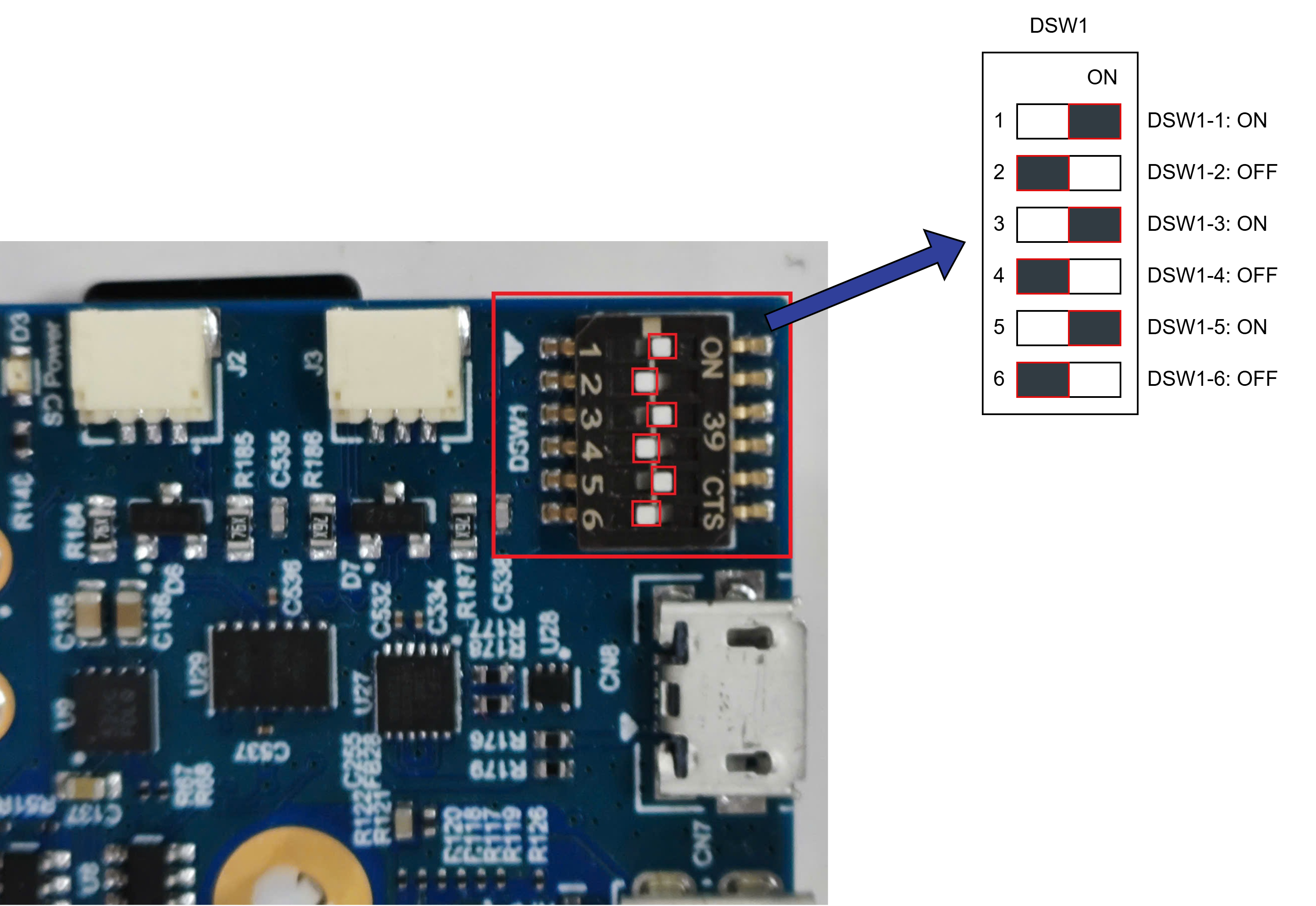
On the RZ/V2H RDK, configure the DSW1 switches as shown below:
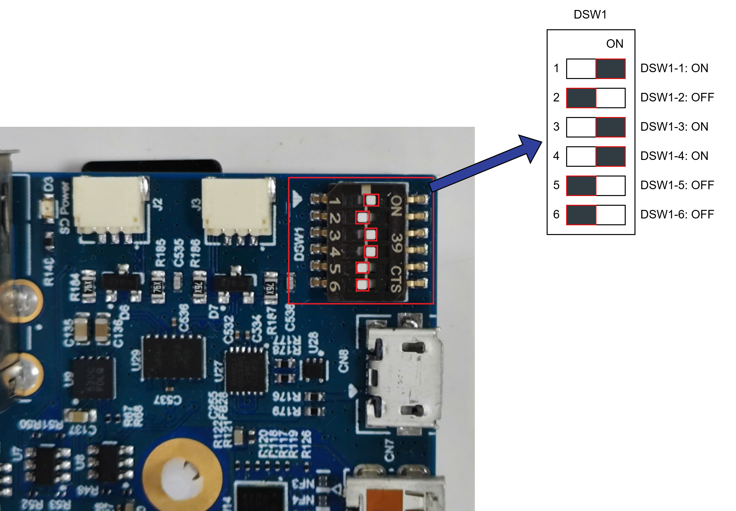
DSW1 microSD card Boot Mode
After that, insert the microSD card and connect the power supply to the board.
Open a terminal emulator (e.g., Tera Term) and connect to the COM port of the board.
The COM port settings are listed below:
Item |
Value |
|---|---|
Baud rate |
115200 |
Data |
8-bit |
Parity |
None |
Stop |
1-bit |
Flow control |
None |
Transmit delay |
0 msec/char |
The board will start the boot process.
Tip
If no serial output is shown at all, try the JTAG reset tip.
If the U-Boot prompt appears but the system does not boot correctly, reset the U-Boot environment variables:
env default -a
saveenv
boot
If you intend to use microSD card boot mode only, proceed to first time boot setup to complete the setup.
Option 2: xSPI boot mode
Follow the instructions below to set up the board.
Install Terminal Emulator
Note
If already installed, skip this step.
Terminal Emulator: Tera Term
Operating Environment: Windows
Write Bootloaders to the Board
Copy the bootloaders files to your Windows PC.
File Name
Description
Flash_Writer_SCIF_RZV2H_DEV_INTERNAL_MEMORY.motFlash writer for RZ/V2H (used in SCIF download mode)
bl2_bp_spi-rzv2h-rdk.srecBoot loader stage 2 binary
fip-rzv2h-rdk.srecFirmware Image Package for RZ/V2H
Connect the Windows PC and Board using a USB-to-microUSB cable.
Change the DSW1 setting to Boot Mode 3 (SCIF download).
DSW1 SCIF Download Mode
Connect the power cable.
Open Tera Term and configure:
Setup → Terminal:
Item
Value
New-line
Receive: Auto / Transmit: CR
Setup → Serial Port:
Item
Value
Baud rate
115200
Data
8-bit
Parity
None
Stop
1-bit
Flow control
None
Transmit delay
0 msec/char
Open File → Send file… and send the Flash Writer file (
.mot) as text.If the following message is displayed, the file transfer was successful:
Flash writer for RZ/V2x Series Vx.xx xxx.xx,20xx
Product Code : RZ/V2x
Next, enter the
XLS2command in the terminal:> XLS2 ===== Qspi writing of RZ/V2x Board Command ============= Load Program to Spiflash Writes to any of SPI address. Program size & Qspi Save Address ===== Please Input Program Top Address ============ Please Input : H'
Enter
8101e00. The log continues:Please Input : H'8101e00 ===== Please Input Qspi Save Address === Please Input : H'
Enter
00000. The log continues:Please Input : H'00000 please send ! ('.' & CR stop load)After the “please send!” message, open File → Send file… and send the
bl2_bp_spi-rzv2*.srecfile as text from the terminal software.If prompted to clear data, enter
y:SPI Data Clear(H'FF) Check : H'00000000-0000FFFF, Clear OK?(y/n)
The following log will be displayed. The end address depends on the version of IPL:
Write to SPI Flash memory.
======= Qspi Save Information =================
SpiFlashMemory Stat Address : H'00000000
SpiFlashMemory End Address  : H'00036D17
===========================================================
Enter
XLS2on the terminal again to get the following messages:> XLS2 ===== Qspi writing of RZ/V2x Board Command ============= Load Program to Spiflash Writes to any of SPI address. Program size & Qspi Save Address ===== Please Input Program Top Address ============ Please Input : H'
Enter
00000. The log continues:Please Input : H'00000 ===== Please Input Qspi Save Address === Please Input : H'
Enter
60000. The log continues:Please Input : H'60000 please send ! ('.' & CR stop load)After the “please send!” message, open File → Send file… and send the
fip-rzv2*.srecfile as text from the terminal software.If prompted to clear data, enter
y:SPI Data Clear(H'FF) Check : H'00000000-0000FFFF, Clear OK?(y/n)
The following log will be displayed. The end address depends on the version of IPL:
Write to SPI Flash memory.
======= Qspi Save Information =================
SpiFlashMemory Stat Address : H'00060000
SpiFlashMemory End Address  : H'0011C2EE
===========================================================
Power off the board and change DSW1 to configure the boot mode.
Set up xSPI U-Boot Configuration
Insert the microSD card into the board.
Change DSW1 to Boot Mode 2 (xSPI boot):
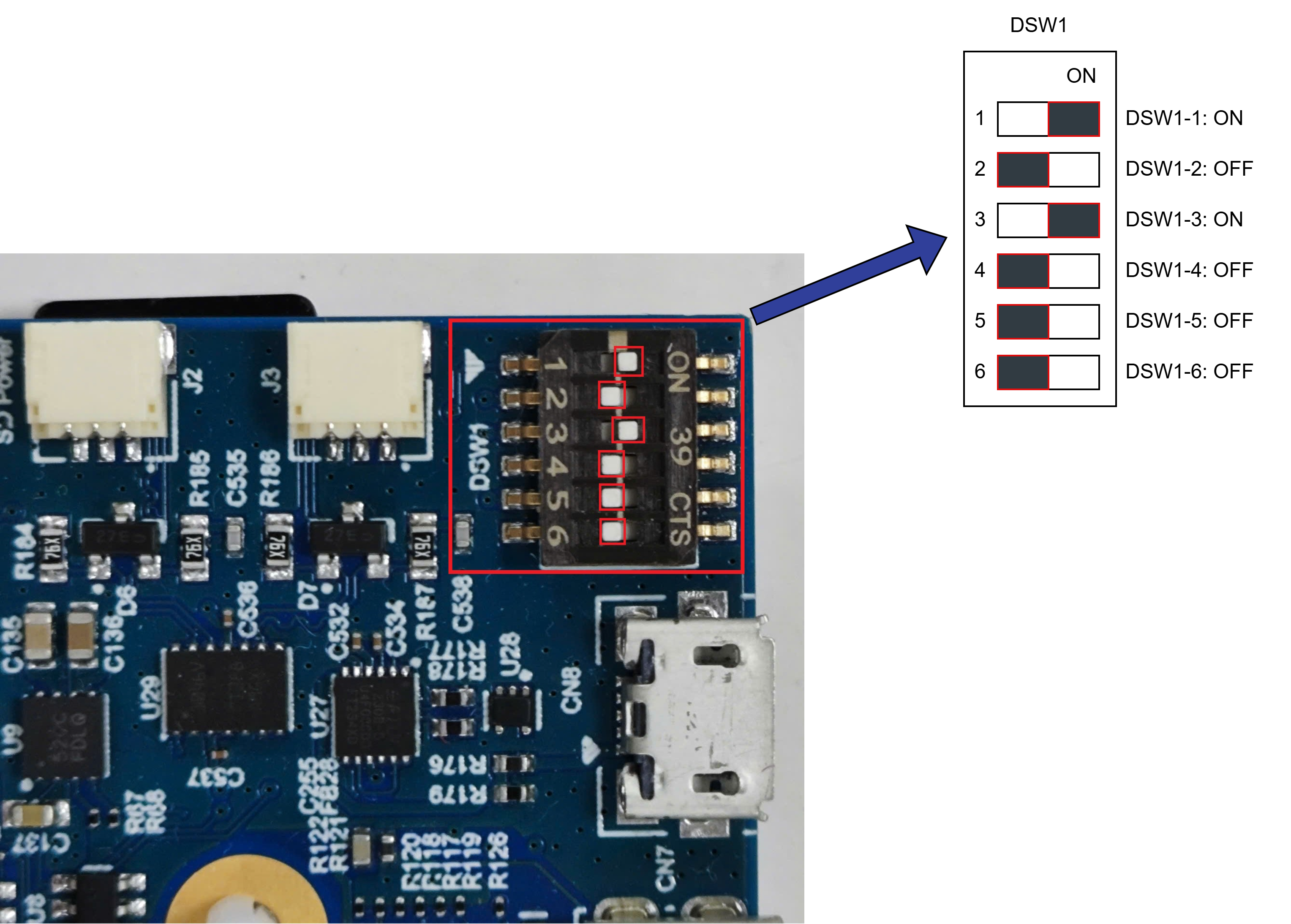
DSW1 xSPI Boot Mode
Connect the board to the PC using a USB-to-microUSB cable.
Power on the board.
Open the terminal emulator and connect to the COM port (same configuration as before).
The board will boot.
Tip
If no serial output is shown at all, try the JTAG reset tip.
If the U-Boot prompt appears but the system does not boot correctly, reset the U-Boot environment variables:
env default -a
saveenv
boot
First Time Boot Setup
The default user credentials for the provided Ubuntu images are as follows:
Image Type |
Username |
Password |
|---|---|---|
Ubuntu 24.04 Server |
ubuntu |
ubuntu |
After powering on the board for the first time, connect to the serial console and check the boot log to verify that Ubuntu boots successfully.
Connect an Ethernet cable to the board and run:
# Check network
ping 8.8.8.8 -c 3
ping bing.com -c 3
Note
The following error may occur during boot, causing no Internet connection even though the Ethernet cable is connected:
ubuntu@ubuntu:~$ dmesg | grep error
[   17.664297] dwc-eth-dwmac 15c30000.ethernet end0: __stmmac_open: Cannot attach to PHY (error: -110)
To resolve this issue, power off the board, unplug the Ethernet cable, power it on, wait until the system fully boots, then plug the Ethernet cable back in.
Perform apt update and resize the microSD card:
sudo apt update
sudo apt install parted
sudo parted /dev/mmcblk0 resizepart 2 100%
sudo resize2fs /dev/mmcblk0p2
Note
The above commands resize the second partition to utilize the full capacity of the microSD card.
If you are using a different partition layout, please adjust the command accordingly (e.g., change the partition number).
Install the ROS 2 Jazzy:
Install ROS 2 Jazzy on the CA55 core (Ubuntu side). You can find and use the provided script here: apt_install_ros2.sh.
Quick installation steps:
wget https://raw.githubusercontent.com/renesas-rdk/ros2_demo_workspace/refs/heads/main/common_utils/apt_install_ros2.sh
chmod +x apt_install_ros2.sh
sudo ./apt_install_ros2.sh
For detailed installation instructions, refer to the official ROS 2 documentation: ROS 2 Jazzy Installation Guide.
(Highly Recommended) Install the RZ/V2H OpenCV Accelerator optimized for Ubuntu 24.04 on the RZ/V2H RDK.
wget -qO install_opencv_arm64.sh https://raw.githubusercontent.com/renesas-rdk/rzv2h_opencv_accelerated_debs/main/install_opencv_arm64.sh
sudo bash install_opencv_arm64.sh
Note
The installation process may report error about missing dependencies during the
dpkgstep. This is expected and will be resolved automatically by the script.(Optional) Add the ROS 2 environment setup to
.bashrc:echo "source /opt/ros/jazzy/setup.bash" >> ~/.bashrc source ~/.bashrc
This completes the Quick Start Guide for RZ/V2H RDK.
Reference
Advanced Boot Options (xSPI): Renesas RZ/V AI SDK Developer Guide
Balena Etcher Official Website: https://www.balena.io/etcher